top of page

Object
In this class we will learn the basics of physical computing.

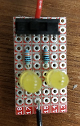
Above is an example of a circuit that includes a switch and two LED's in series. The Schematic diagram shows the flow of electricity from the power source to the switch, through the resistor, into the first LED, into the second LED and then to ground.
Hello Object
What do you want to learn in Object, and what do you already know? What are your superpowers when it comes to this class (coding, fabrication, creative thinking, hardware, etc..)? Do you have any project ideas?
I know almost nothing about physical computing or any of the concepts we will cover in this class, but I am very excited to learn everything I can about circuits and their real word application. I have taken a few classes in computer science (CSCI 1300, CSCI 2700), so that may help with coding. I also conciser myself to be pretty creative. I do not have any project ideas now, but I am sure I will be inspired as soon as I have a better understanding of the materials and techniques we will learn in the first few days of class.


Above is an example of a circuit that includes a switch and two LED's in parallel. The schematic diagram shows the flow of electricity from the power source to the switch, then split into two resistors, then two LED's, and then both currents go to ground.

Digital I/O
Today we soldered the parallel LED circuits we made yesterday. The first two pictures below show the front and back of the soldered breakout board and the final photo shows the switch turned on with the lights illuminated.


Today we were also challenged to create a circuit with at least 2 digital inputs and use either LEDs or neopixels as outputs. We programmed the microcontroller so that each input has a unique output..

The photo above shows the schematic diagram I drew to complete this task. I programmed the microcontroller to make the neopixel strip turn off if no switches are down, to blink blue if the first switch is down, to blink purple if the second switch is down, and blink white if both switches are down. Below is a video and photos of the results as well as a link to the code I wrote.
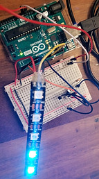


In the code, I used if and else statements to describe the four different combinations of ways the switches could be turned. Within each of these I added a for loop to turn on each light on the neopixel strip individually one after another.
Project 1- Digital and Analog I/O
For this assignment we were required to build an interactive circuit that uses at least two different variable resistors (inputs) and some kind of output (sound, light, movement). We also had to build a custom enclosure for the project that fully hides the electronics.
I chose to build a light box that takes input from a sliding potentiometer and a radial potentionemter. The ouput devices I chose were a neopixel strip and a servo. The sliding potentiometer will control the rotation of the servo and turn on each light in the neopixel strip. I will connect the servo to a door on the box that will turn to reveal the neopixel lights below. As the door opens, the lights of the neopixel strip will turn on one by one, each in a different color. Once the door opened, the color of the lights on the neopixel strip can be cycled through rainbow colors by turning the radial potentiometer. Then, by moving the sliding potentiometer back to the start, the door will close and the lights will change to the original colors before turning off.
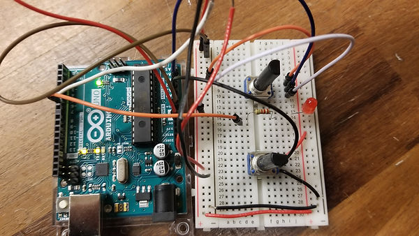
First I built a circuit on a breadboard to make sure I had all the right connections. I then used this prototype to test the code as I wrote it.

The code I wrote for this project is linked below:
https://gist.github.com/sarahenglish/9ed2934f1d85ebfa97c7c38bd7dd44b6
Once the circuit and code was all running properly I was able to focus on the enclosure. I chose to build it mainly with cardboard. The window over the neopixel strip was laser cut from clear acrylic and then spray painted to give it a frosted glass effect. Below you can see the box, door, and window that I constructed the enclosure from. I have also included PDF attachments of the illustrator files I created to laser cut these pieces. I used a website called maker case to get the basic dimensions for the box and then added all the other features myself.


The next step was to solder all the connections onto a piece of breakout board and then cover those connections with hot glue to avoid contact between conductive materials that would create a short circuit. The glue also helped to hold all the pieces in place. I would then attach the input slider, and dial as well as the output servo and neopixel strip to the box. The photos below show the soldered and glued breakout board as well as the interior of the completed box.


Below is a photo of my finished project. I connected a wall plug through a hole in the back of the box for power.

Here is a video of my light box in action!
Final Thoughts:
This was a very fun project to build. I was very excited about the fact that I was able to make the sliding potentiometer control both the neopixel strip and the servo at the same time. I struggled for a while to come up with a way to make the radial potentiometer make the neopixels cycle through rainbow colors. I thought at first that I would have to use 3 inputs to control each of the RGB values, but I ended up writing in RGB values for 16 colors and having them cycle. The main thing I would have changed if I had to do this project over again would be the material for the container. Instead of cardboard I would have used white acrylic. I think based on the shape of the window and the colors I chose, the box has a bit of a rainbow theme. By making the box white, I could have pushed that theme a little bit more. The white box would have suggested white clouds around a rainbow without being to glaringly obvious. I think the white material for the box could have helped to give my box a more focused theme and enhance the overall aesthetic quality.
Serial Communication
For this assignment, we were tasked with building an interactive interface using P5JS that visualizes or utilizes data from a collection of analog sensors. The interaction should include physical inputs (at least 2) and outputs (at least 1 piece of hardware with 2+ modes) in addition to a dynamic screen-based display.
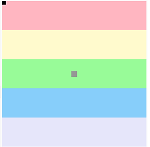
I chose to create a little game. I used input from two radial potentiometers and output onto a neopixel strip and a red LED. My screen display shows colored stripes across the canvas with a small square in the very center. There is a another small square, and its position is controlled by two dials. One dial controls position in the x-direction and the other controls it in the y-direction. As the dials are turned and the square moves across the canvas, a neopixel strip lights up in accordance with the color stripe that the small box is in on the screen. The object of the game is to move the small moving square into the small square in the center of the canvas. When you do this, the neopixel strip turns white and the red LED will turn on.
Below are links to the code I used in P5 and the code I used in Arduino. There is also a video of the game in action.
P5: https://gist.github.com/sarahenglish/eadb3966d84d0b90b647b3a23c163a96
Arduino: https://gist.github.com/sarahenglish/dfd52b688e412123f9788c317a1c524c
Final Project Proposal
For the final project, we must build a physically interactive system . The focus in this assignment should be on careful and timely sensing of the relevant actions of the person or people it is designed for, and on a clear, prompt, and effective response. We must spend a significant focus on the final enclosure of this project. We will push our abilities to produce something that utilizes what we have learned in the class and that is meaningful or useful in some manner to ourselves or the world.
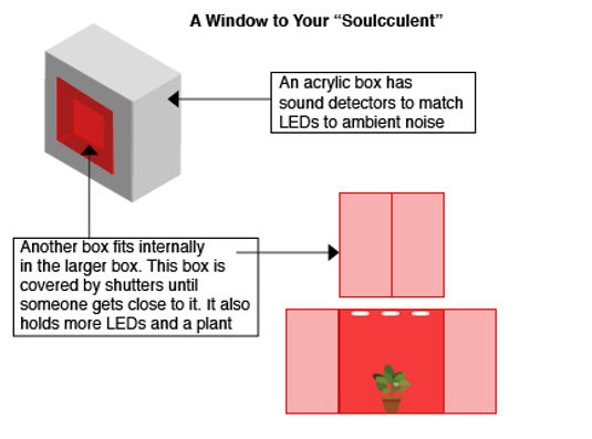
I have chosen to work in a group with Zayna and Bella. We have decided to create an interactive window to place in an indoor space somewhere in the ATLAS building. We hope that with this project we can reach students and staff in the space and provide them with a moment of calm in their busy lives.
We will build a large box with a window that opens to a smaller box inside. The large box will sense ambient noise and a light display will react in response to the noise. When someone approaches the box, the window shutters will open to reveal a plant in a flower box with a calm, glowing sky in the background. The user can then touch and interact with the plant. The more time spent interacting with the plant will cause the background to have a warmer glow.

The outer box will be built from black and frosted acrylic. Neopixel strips will be attached behind the frosted acrylic that will be controlled with sound detector sensors that will pick up ambient noise. An ultrasonic sensor will also be attached to the outer box. When a person comes close enough to the box, servo motors will be activated and the window shutters will open. Wires and conductive tape will be attached to the plant and pressure sensors will be placed under pebbles and other decorative elements on the windowsill. As these sensors receive more input, the background of the window, made from neopixels and frosted acrylic, will slowly change to show a warmer, brighter color.
Things We Need:
-
Shutter hinges
-
2 audio sensors
-
A bunch of neopixels
-
2 ultrasonic sensors
-
Acrylic sheets
-
Shutters (fabricated with wood)
Things We Have:
-
3 arduinos
-
2 servo motors
-
Frosted spray paint if we can’t find frosted acrylic


bottom of page